Adding a Resistor in Series With a Load Will Cause
Next you add a second one ohm resistor as in the circuit with V2. A load resistor essentially serves the same purpose as the incandescent bulb in the solution described above it simulates an electrical load drawing sufficient current to the dimmer switch.

Resistors In Series Series Connected Resistors
However having a series resistor connected to the speaker means that each one gets only 12 of the total power delivered.
. Simulate this circuit Schematic created using CircuitLab. An example is a standard Light Emitting Diode LED which has a current limit of 20 mA. The resistor limits the amount of current that the op-amp has to can sink or source ensuring that the output transistors are never driven into saturation even when the op-amp is charging a completely empty capacitor which briefly resembles a dead short to ground which will almost certainly cause saturation.
The second resistor is a second path for the current. The resistor impedes current flow decreasing total circuit current so the current going through the resistorthrough all componentsis decreased but the same potential difference still exists at the source theres. In fact since capacitors simply add in parallel in many circuits capacitors are placed in parallel to increase the capacitance.
The resistor will offer 5 Ω of resistance to AC current regardless of frequency while the capacitor will offer 265258 Ω of reactance to AC current at 60 Hz. An amp that can drive an 8 ohm speaker at 150W can drive a 4 ohm speaker at 75W. If you have a capacitor in place after a junction of two resistors of different resistances the capacitor will be charged by the resistor with less resistance since more current flows through it.
Between adding an incandescent bulb to the circuit and using a load resistor the resistor is probably the preferred solution as its likely to require less maintenance long-term. When capacitors and resistors are connected together the resistor resists the flow of current that can charge or discharge the capacitor. The resistor will offer 5 Ω of resistance to AC current regardless of frequency while the inductor will offer 37699 Ω of reactance to AC current at 60 Hz.
So a resistor is used in series with many components to reduce the current to avoid damaging them. In series the more resistance you have the longer it will take to charge. Notice how the mid scoop is wider and the max bass and treble are balanced on the right with the 56k slope resistor.
Because the resistors resistance is a real number 5 Ω 0 or 5 j0 Ω and the inductors. The lamps each get more dim with each load added because in a series circuit the amount of voltage per load is determined by the total voltage divided by the amount of loads. Since changes in the load current would only.
So adding up the total capacitance in parallel is much simpler than adding them in series. He is asking if adding an 8 ohm resistor in series with his existing 8 ohm speaker would work. R V I.
The larger the resistor the slower the chargedischarge rate. If a voltage supply is connected directly to the LED without the use of a current limiting resistor you risk blowing the LED. A mid or high amp wont be driven this hard but a sub amp may very well be.
Series resistor inductor circuit. For exampleif you had 6 2 volt 20 milliamp LEDs across a 12 volt DC power supply then you would need a resistor which has a voltage drop of 10 volts across it can pass 20 milliamps like this -. So electric field tells us about the force push or pull that would be felt by a charge at a given distance it is Felectricq because it is for any given.
Either way capacitance will not change. If a voltage is applied to a capacitor through a series resistor the charging current will be. Yes either in series with each other or one common resistor on the positive or negative supply side.
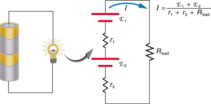
To verify that resistances in series do indeed add let us consider the loss of electrical power called a voltage drop in each resistor in Figure 2According to Ohms law the voltage drop V across a resistor when a current flows through it is calculated using the equation V IR where I equals the current in amps A and R is the resistance in ohms Ω. Adding a 4 ohm resistor in series will bring the total resistance speaker load in Ohms up to the safe level of 8Ω. A higher value tone slope resistor will also lighten the impedance load of the tone stack and therefore boost gain.
Adding a series resistor increases the series resistance which decreases the series current when driven by a voltage source. For example if a circuit designer wants 044µF in a certain part of the circuit he may not have a 044µF capacitor or. In a series circuit the current is the same for all of.
The current in a series circuit is everywhere the same. 100k Tone Slope resistor on the left 56k on the right. Adding a resistor to a circuit increases the total energy that the voltage needs to provide so it has less energy to provide to other parts of the circuit.
Consider the following circuits. Its one volt across a one ohm resistor with one amp of current. Current lags applied voltage by 0o to 90o.
So if your amp can put out 150W into an 8 ohm load it can safely put 75W into a 4 ohm load but can be overdriven by a too-high input signal. Yes it will increase the nominal load the amp sees to 16 ohms BUT it will also completely obliterate any amplifier damping which for bass guitar is not a good option especially with an amp that already has a low DF. The effect is subtle but some prefer the 56k slope.
Because the resistors resistance is a real number 5 Ω 0 or 5 j0 Ω and the capacitors reactance is an imaginary number 265258 Ω -90 or 0 - j265258 Ω the. With a current source the current leaving the source is constant but if you add resistors in series the current going through each resistor will decrease accordingly per resistor added. Adding a 606K resistor in parallel with the load would cause the total current draw to be about 1000mA-0005mA requiring the upper resistor be changed to 6K.
Also I did a quick Google search on the phrase current is constant in series circuit and here are quotes from the top links returned. The larger the capacitor the slower the chargedischarge rate. The first circuit with V1 is your initial circuit.
If one just used a series resistor sized for the 10uA case 600K it would drop only 3V at 5uA feeding 9 volts to the load and 9V at 15uA feeding 3 volts to the load.

Resistors In Series Series Connected Resistors
Resistors In Series And Parallel Boundless Physics

What Is The Purpose Of A Resistor In Series With A Potentiometer Electrical Engineering Stack Exchange
No comments for "Adding a Resistor in Series With a Load Will Cause"
Post a Comment